CPU Monitor program
One of the advantages of the WD
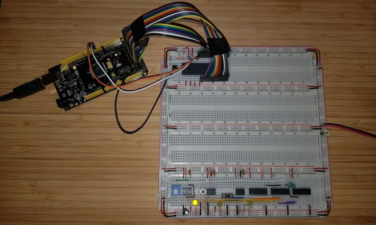
One of the advantages of the WDC60C02 is the fully static design. This makes it possible to stop the CPU clock at any time without the CPU loosing its status. You can then restart the clock and the CPU continues where it left off. This enables us to monitor the CPU execution using and Arduino Mega 2560.
Which is his own 8 bit computer with 256kb flash memory but only 8kb of RAM. And an almost endless row of I/O ports. Enough to monitor both the address bus and the data bus of the 65C02.
The Arduino is programmed in C++ and Ben Eater show a very simple monitor program. However I thought it had a couple of flaws. Most notably the use of the data type char when byte would be more appropriate. As well as code duplication where a function could be used. And lastly using a function before declaration without a function prototype.
Of course since it's C++ I could not help but encapsulating some of the logic inside a class. That C++ doesn't have the variable length array (VLA) feature from C is a bit of a disappointment.
Anyway, the the improved and potentially over engineered version of the monitor application.
/**
 * Bus class handles reading the 6050 address and data bus
 */
class Bus
{
private:
    /**
     * Size of the 6502 bus (16 for address bus and 8 for data bus).
     */
    size_t const Size;
    /**
     * Arduino I/O lines the 6502 bus is connected to.
     */
    byte const* Lines;

public:
    /**
     * initialise Bus.
     *
     * @param Size of the 6502 bus (16 for address bus and 8 for data bus).
     * @param Arduino I/O lines the 6502 bus is connected to.
     */
    Bus (const byte Lines[], size_t Size) :
        Size (Size),
        Lines (Lines)
    {
    } // Bus

    /**
     * initialize the Arduino I/O lines used to monitor the 6502 bus to INPUT.
     */
    void Init () const
    {
        for (unsigned int i = 0;
             i < Size;
             i++)
        {
            pinMode (Lines[i], INPUT);
        } // for

        return;
    } // Init

    /**
     * read the but date from the Arduino I/O lines.
     *
     * @return value read.
     */
    word Read () const
    {
        word Retval = 0;

        for (unsigned int i = 0;
             i < Size;
             i++)
        {
            auto bit = digitalRead (Lines[i]) == HIGH ? 1 : 0;

            Serial.print (bit);

            Retval = (Retval << 1) + bit;
        } // for

        Serial.print (" ");

        return Retval;
    } // Read
};

/**
 * Address bus
 */
static Bus const A = Bus (
    (byte[16]) {22, 24, 26, 28, 30, 32, 34, 36, 38, 40, 42, 44, 46, 48, 50, 52},
    16);

/**
 * Data bus
 */
static Bus const D = Bus (
    (byte[8]) {39, 41, 43, 45, 47, 49, 51, 53},
    8);

/**
 * Clock pin
 */
static byte const PHI2 = 2;

/**
 * executed at every clock pulse of the monitored 6502
 */
static void On_Clock ();

/**
 * Read/Write pin
 */
static byte const RWB = 3;

/**
 * Setup Arduino
 */
extern void setup ()
{
    Serial.begin (115200);
    Serial.println ();
    Serial.println ("Start 6502 Monitor");

    // Setup address bus pins
    //
    A.Init ();

    // Setup data bus pins
    //
    D.Init ();

    // Setup clock pin
    //
    pinMode (PHI2, INPUT);
    attachInterrupt (digitalPinToInterrupt (PHI2), On_Clock, RISING);

    // Setup read/write pin
    //
    pinMode (RWB, INPUT);

    return;
} // setup

extern void loop ()
{
    // do nothing

    return;
} // loop

/**
 * executed at every clock pulse of the monitored 6502
 */
static void On_Clock ()
{
    auto Address = A.Read ();
    auto Data = D.Read ();
    auto Read_Write = digitalRead (RWB) == HIGH ? 'r' : 'W';
    char Output[15];

    snprintf (Output, sizeof Output, "%04x %c %02x", Address, Read_Write, Data);
    Serial.println (Output);

    return;
} // On_Clock
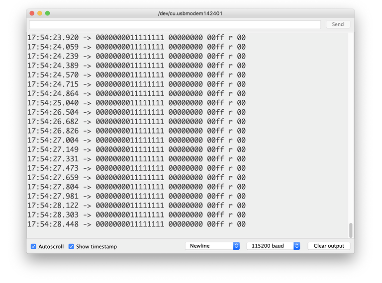
However there were some bad news here. The CPU is actually dead as the output look like this:

Monitor output.
I suspect the failing the power supply fried then chip. It behaves now very strangely.
You find the full source code with makefiles, project files and everything on GitLab: 6502Tutorial — Arduino/Monitor