Ben Eater 6502 Kit — Day 10 – Attach ROM to CPU
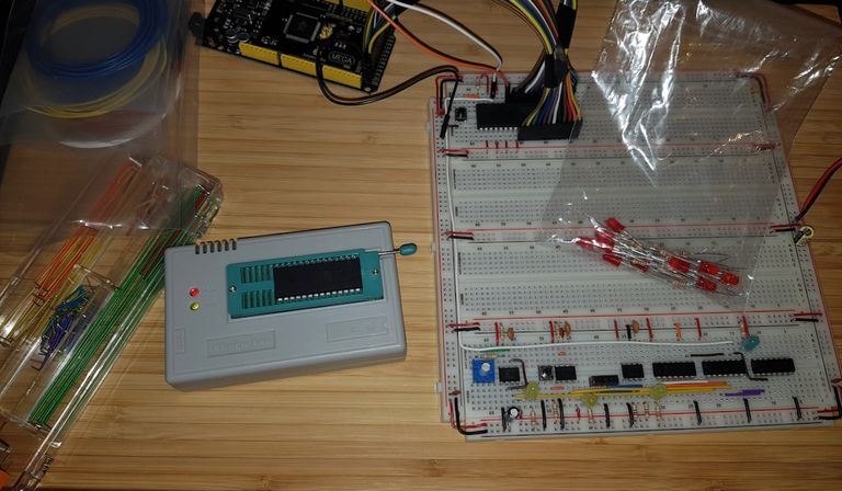
After I checked the CPU by hardcoding a NOP operation with 8 1kΩ resistors the next step is adding a ROM to for the future programs. Or better an EEPROM (electrical erasable read only memory). I already filled the ROM with NOP in Ben Eater 6502 Kit — Day 8. All I need to do is attach the ROM. Which is quite a bit of work:
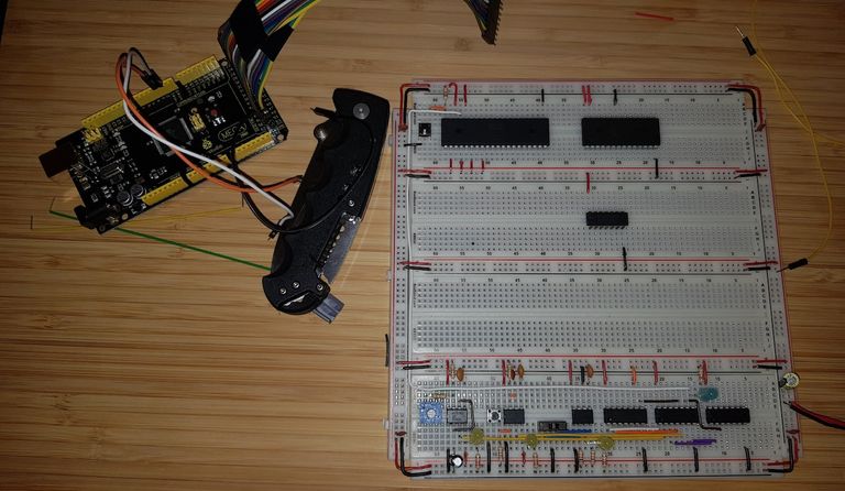
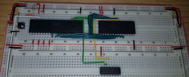
Placing the ROM and the NAND chip
All memory added to a computer need a memory management unit to generate the chip select signals o the correct chip is activated. This project uses a simple 4×2 NAND to do the job. Mind you, I have an 2×4 AND and 1×8 NAND as well to make it more sophisticated.
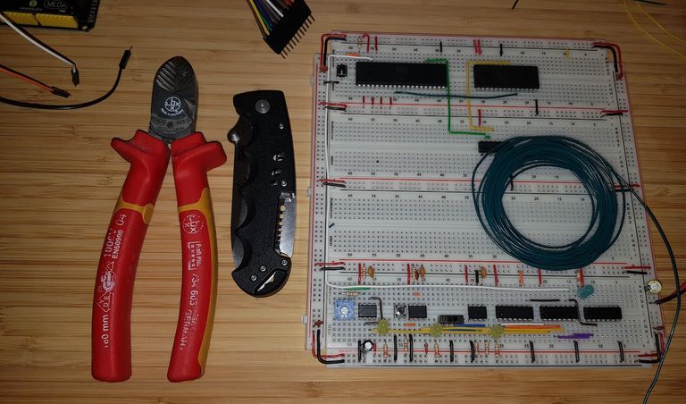
Connect the chip select.
Connect the first address bus line
The placement of the address lines on the AT28C256 is rather chaotic.
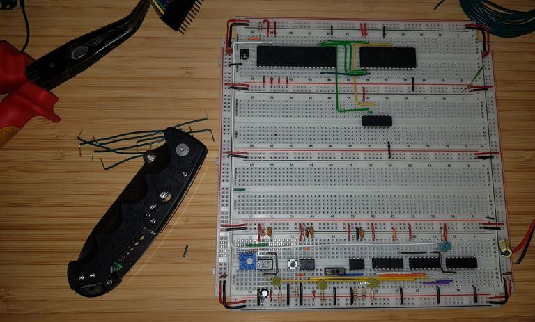
Finished with the address lines
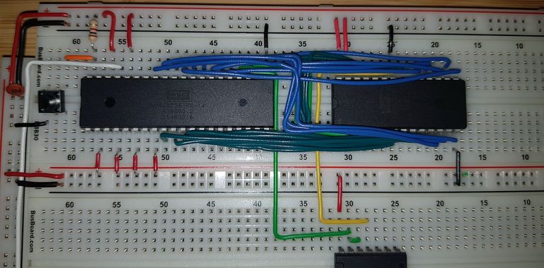
Added the data lines
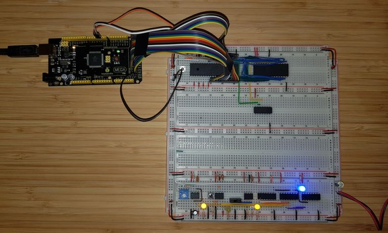
Attached the Arduino
After attaching the ROM I tested the CPU. The result was as expected: After the reset sequence the CPU started execution at EAEA₁₆ as described in the video.
You find the full source code with makefiles, project files and everything on GitLab: 6502Tutorial — Tools/Create_NOP