Macro Assembler
Up until now programming was done in hex code. Which is quite cumbersome and error prone. It's time to switch to more powerful tools. But first I have to repair EEPROM. I pulled the chip out a little to enthusiastically.
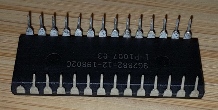
Lost one of it's feed
I'm just not a flawlessly perfect as Ben Eater is. Good that I already ordered some spare EEPROMs so this one only has to arrive until the spare EEPROMs arrive.
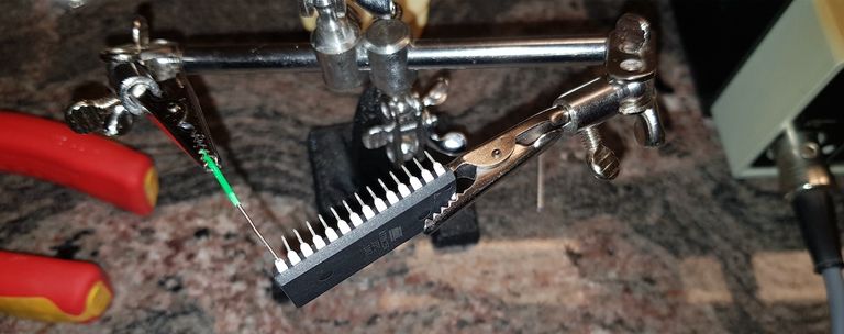
Attach a wire to replace the missing pin
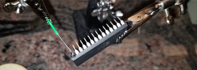
Soldering the wire
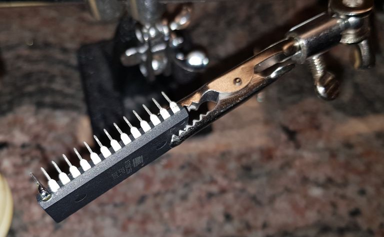
Cut the wire to the desired length.
Now that the EEPROM is repaired we can develop the program to running light for the LEDs. I have decided to use the macro assembler from the CC65 toolchain which is a little more powerful but comes at the cost of needing a little extra configuration.
Linker
The CC65 toolchain consists of a C compiler, a macro assembler and a linker. The latter needs to know the memory layout of the destination computer. With the extended memory management I implemented the memory layout looks like this:
MEMORY
{
   ZP:  file = "", start = $0000, size = $0100;
   STACK: file = "", start = $0100, size = $0100;
   RAM: file = "", start = $0200, size = $7A00;
   IO:  file = "", start = $7C00, size = $0400,
   ROM: file = %O, start = $8000, size = $7FFA, fill = yes, fillval = $EA;
   BRKINFO: file = %O, start = $FFFA, size = $0006, fill = yes, fillval = $00;
}

SEGMENTS
{
   ZEROPAGE: load = ZP, type = rw;
   DATA: load = RAM, type = rw;
   CODE: load = ROM, type = ro;
   RODATA: load = ROM, type = ro;
   HEADER: load = BRKINFO, type = ro;
}
Note that only the ROM and BRKINFO are written to the output file.
Macro Assembler
In return for the little extra work you get a powerful macro assembler and even a C compiler. But I won't use the latter. Using a macro assembler I can save myself code duplication. Which is not yet a problem right now but will be in future. So here the totally over engineered macro assembler code:
ORB     =     $7F00
DDRB     =     $7F02

NMIB     =     $FFFA
RESB     =     $FFFC
IRQB     =     $FFFE

;;
;   Set VIA data directon register B
;
.macro     Set_B   Value
.ifnblank     Value
    LDA     Value
.endif
    STA     DDRB
.endmacro

;;
;   Set VIA output register B
;
.macro     Out_B   Value
.ifnblank     Value
    LDA     Value
.endif
    STA     ORB
.endmacro

;;
;   Logical rotate right accumulator
;
.macro     L_ROR
.local     Skip
    LSR
    BCC     Skip
    ORA     #$80
Skip:
.endmacro

.segment    "CODE"

Do_RES:     Set_B   #$FF
    Out_B   #$50

Loop:     L_ROR
    Out_B
    BRA     Loop

Do_NMI:     RTI

Do_IRQ:     RTI

.segment    "HEADER"
.word     Do_NMI
.word     Do_RES
.word     Do_IRQ
If you look closely you will notice that I don't use the ROR command. Instead I use an L_ROR macro. The macro does a logical rotate right (without carry) so there are always two LED lit.
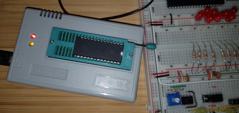
Write the program into the EEPROM
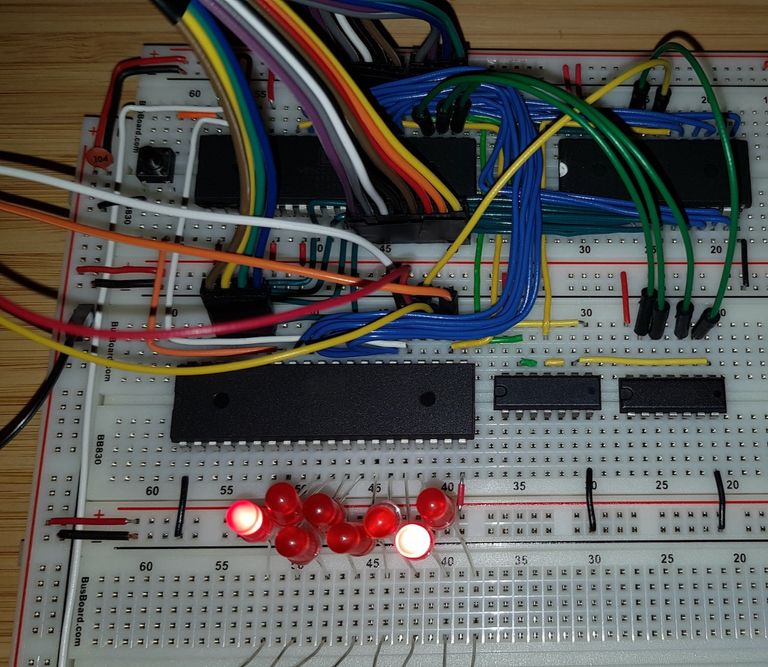
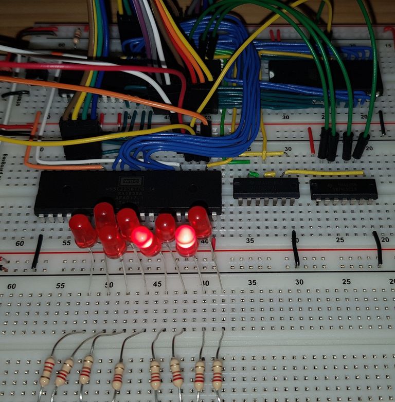
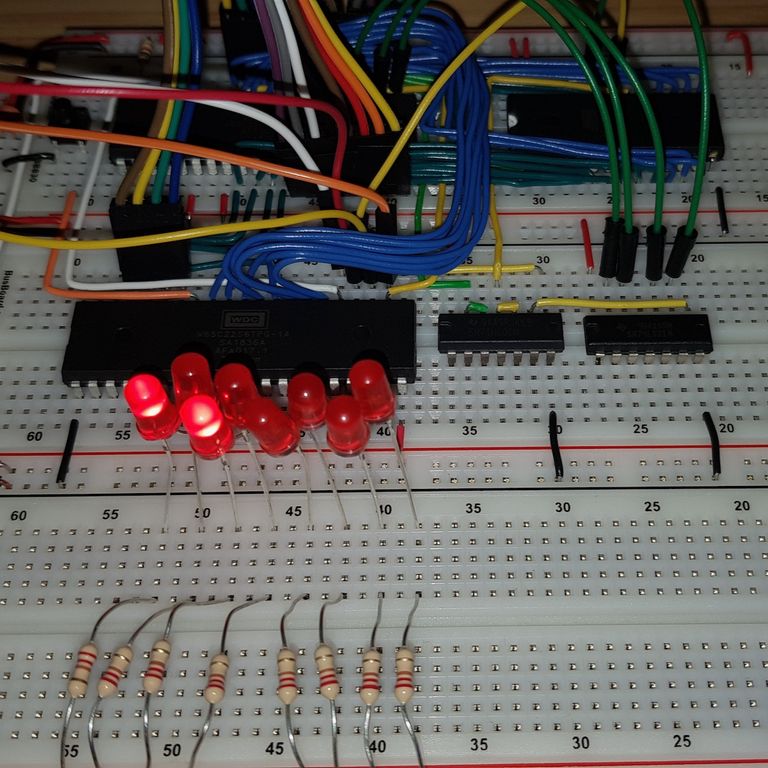
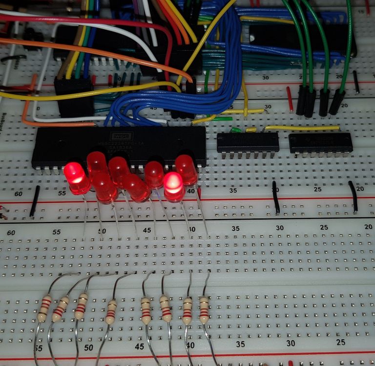
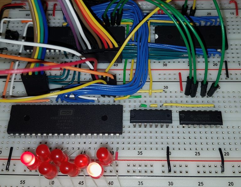
And here a few pictures of the running program:
You find the source code for the program with makefile, linker configuration file and assembler source code on GitLab: 6502Tutorial — Tools/Create_LED