
I continue with this series of tutorials for all music lovers, dedicated to the development of MIDI, a technological standard that describes a protocol, a digital interface and connectors that allow various electronic musical instruments, computers and other related devices to connect and communicate with each other.1 A simple MIDI connection can transmit up to sixteen channels of information that can be connected to different devices each.
Continúo con esta serie de tutoriales para todos los amantes de la música, dedicados al desarrollo de MIDI un estándar tecnológico que describe un protocolo, una interfaz digital y conectores que permiten que varios instrumentos musicales electrónicos, ordenadores y otros dispositivos relacionados se conecten y comuniquen entre sí.1 Una simple conexión MIDI puede transmitir hasta dieciséis canales de información que pueden ser conectados a diferentes dispositivos cada uno.
Hardware implementation. / Implementación en el hardware.
The original design was developed after a series of meetings held by the main musical instrument manufacturers in Japan and the United States. The design of the control circuit allows the transmission of data from one instrument to another, or from a computer to an instrument. The processor needed to handle the messages is 8 bits that are transmitted serially. This decision was made based on the cost/benefit ratio. Parallel transmission would allow all 8 bits to be transmitted simultaneously, increasing the transmission speed, but the number of lines that would need to be connected would have to be at least 8, and therefore the production cost would also increase.
In serial transmission only two lines are used: on one the data bits are sent one after the other, and on the other the receiving device notifies the sender if there are parity errors in the data stream. So serial transmission was chosen despite being slower than parallel transmission, because it had the advantage of using a simpler connector and being much cheaper, as the marketing index was thought of in a price range affordable to most personal computer users and musicians who used synthesizers and drum machines of the time.
The transmission speed is 3125 serial words (Words) per second, that is 31.25 Kbaud. This speed is 38.5% faster than an RS232 interface, which, up to its third revision (C), officially allows transmissions of around 20,000 baud, specifically 1920 words per second (although the interface chips in a PC enable up to 115,200 baud if the cabling is not too long). The clock speed of 31.25 Kbaud is relatively high compared to serial transmission, but it is not fast enough, as we will see later, when we explain the anatomy of MIDI messages in detail.
A MIDI message has 10 bits transmitted per byte. The transmission of a 3-byte message takes approximately 1 millisecond. Because MIDI is transmitted serially, it is very likely that two or more musical events that occur simultaneously when sent one after the other will not be played back at exactly the same instant in the receiver. However, this is fast enough for these events to be perceived as simultaneous, even though they are not numerically so. On a MIDI keyboard, when 10 keys are played simultaneously, there is no perceived latency, since the total transmission of this event lasts about 10 ms. This was explained by the German doctor Helmut Haas in his doctoral thesis in 1949 as follows: "if several independent sounds reach our brain in an interval of less than 50 ms, it fuses them and interprets them as one."
MIDI is transmitted asynchronously, so each byte must be defined for the receiving instrument. For this, an ACIA chip (Asynchronous Communications Interface Adaptor) such as the Motorola 6850 is used, which adds two extra bits to each byte of the master instrument. It starts with "0", as a start bit, followed by the 8 serial data bits and ends with "1", called the stop bit. This 10-bit word is transmitted to the receiving instrument, where a second ACIA chip converts it back into the actual eight bits of data.
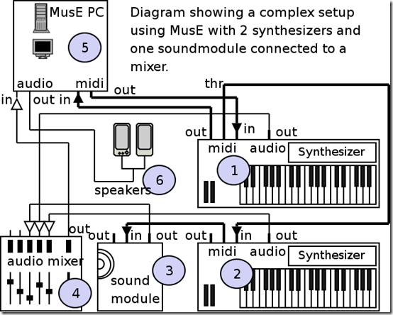
The ACIA chip is protected within the circuit by opto-isolation. An opto-isolator is a device that uses photoelectric cells to allow two unconnected circuits to exchange signals while remaining electrically isolated. In the case illustrated below, the isolation is provided by the Sharp PC-900 IC.
midi_complex_setup
El diseño original se desarrolló después de una serie de reuniones que celebraron los principales fabricantes de instrumentos musicales de Japón y Estados Unidos. El diseño del circuito de control permite la transmisión de datos de un instrumento a otro, o de un computador a un instrumento. El procesador necesario para manejar los mensajes es de 8 bits que se transmiten en serie. Esta decisión se tomó en base a la relación costo/beneficio. La transmisión en paralelo posibilitaría que los 8 bits se transmitieran simultaneamente, aumentando la velocidad de transmisión, pero con ello el numero de lineas que necesitarían estar conectadas debería ser de al menos 8, y por tanto el costo de producción también aumentaría.
En la transmisión en serie solo se emplean dos lineas: en una se envían los bits de datos uno detrás del otro, y en la otra el dispositivo receptor avisa al emisor si hay errores de paridad en la corriente de datos. Así que la transmisión en serie fue elegida a pesar de ser más lenta que la paralela, porque tenía la ventaja de usar un conector más sencillo y de ser mucho mas barata, pues el índice de comercialización fue pensado en una gama de precios asequible a la mayoría de usuarios de computadores personales y músicos que empleasen sintetizadores y máquinas de ritmos de la época.
La velocidad de transmisión es de 3125 palabras en serie (Words) por segundo, esto es 31.25 Kbaudios. Dicha velocidad es 38.5% veces más rápida que una interface RS232 que hasta su tercera revisión (C), permite oficialmente una transmisión cercana a los 20000 baudios, concretamente a 1920 palabras por segundo (aunque los chips de interface en un PC habilitan hasta 115200 baudios si el cableado no es muy largo). La velocidad de reloj de 31.25 Kbaudios es relativamente elevada con respecto a la transmisión en serie, pero no es lo suficientemente rápida como veremos más adelante, cuando expliquemos en detalle la anatomía de los mensajes MIDI.
Un mensaje MIDI tiene 10 bits transmitidos por cada byte. La transmisión de un mensaje de 3 bytes dura aproximadamente 1 milisegundo. Debido a que MIDI se transmite en forma serial, es muy probable que dos o más eventos musicales que ocurran simultaneamente al ser enviados uno detrás de otro, no se reproduzcan exactamente en el mismo instante en el receptor. Sin embargo esto es lo suficientemente rápido como para que esos eventos se perciban como simultáneos, aunque a nivel numérico no ocurra así. En un teclado MIDI, al tocar simultaneamente 10 teclas, no se percibe latencia, ya que la transmisión total de este evento dura unos 10 ms. Esto lo explicó el medico alemán Helmut Haas en su tesis doctoral en 1949 así: ¨si varios sonidos independientes llegan a nuestro cerebro en un intervalo inferior a 50 ms éste los fusiona y los interpreta como uno sólo¨.
MIDI se transmite de forma asincrónica, por lo cual ha de definirse cada byte para el instrumento receptor. Para ello se emplea un chip ACIA (Asynchronous Communications Interface Adaptor) como el Motorola 6850, que agrega dos bit extas a cada byte del instrumento maestro. Empieza con ¨0¨, como un bit de arranque (start) , seguido de los 8 bits de datos en serie y termina en ¨1¨, llamado el bit final (stop). Esta palabra de 10 bits se transmite al instrumento receptor, donde un segundo chip ACIA, lo vuelve a convertir nuevamente en los ocho bits de los datos reales.
El chip ACIA, esta protegido dentro del circuito por optoaislamiento. Un optoaislador es un dispositivo que usa celdas fotoeléctricas para permitir que dos circuitos no conectados intercambien señales, permaneciendo eléctricamente aislados. En el caso ilustrado a continuación, el aislamiento lo proporciona el IC Sharp PC-900.
MIDI Messages. / Mensajes MIDI.
We previously explained that a MIDI message has 10 bits transmitted serially. The 8 middle bits form the MIDI byte, of which there are two types: status bytes and data bytes. Within the structure of the MIDI message, the status byte is also called the header byte, since it is the one transmitted first. All status bytes have the value of the most significant bit at “1”. Thus, the status bytes start at 10000000 and end at 11111111. In hexadecimal, it is the range from 0x80 (128 decimal) to 0xFF (255 decimal).
As a consequence, only three bits of the most significant nib are available to indicate the message type. This means that there is a limit of 8 different message types: 7 channel messages, whose range is between 0x80 and 0xEF (between 128 and 239 decimal), and the system exclusive messages (sysex messages), limited between 0xF0 and 0xFF.
This also means that all data bytes are limited to the range between 0x00 and 0x7F (between 0 and 127 decimal), since this is the range in which the most significant bit has the value “0”.
A data byte is always preceded by either another data byte or a status byte. In other words, all MIDI messages are transmitted in this order: a status byte first, followed by one or two data bytes. The exception to this structure is system exclusive messages, which can contain an indefinite amount of bytes and differ from normal data bytes in that they range from 0x00 to 0xFF (0 to 255 decimal).
Anteriormente explicabamos que un mensaje MIDI tiene 10 bits transmitidos en serie. Los 8 bits intermedios forman el byte MIDI, del cual existen dos tipos: bytes de estado (status bytes) y bytes de datos (data bytes). Dentro de la estructura del mensaje MIDI, el byte de estado es tambien llamado byte de encabezamiento, puesto que es el que se transmite primero .Todos los bytes de estado tienen el valor del bit más significativo en ¨1¨. De esta manera, los bytes de estado comienzan en 10000000 y terminan en 11111111. En hexadecimal, es el rango comprendido desde 0×80 (128 decimal) hasta 0xFF (255 decimal).
Como consecuencia, solo tres bits del cuarteto mas significativo están disponibles para indicar el tipo de mensaje. Esto significa que hay un límite de 8 tipos de mensajes diferentes: 7 mensajes de canal (channel messages), cuyo intervalo comprende entre 0×80 y 0xEF (entre 128 y 239 decimal), y los mensajes exclusivos de sistema (sysex messages), limitados entre 0xF0 y 0xFF.
Esto también significa que todos los bytes de data quedan limitados al intervalo entre 0×00 y 0x7F (entre 0 y 127 decimal), puesto que este es el rango en el cual el bit mas significativo tiene el valor “0″.
Un byte de data siempre esta precedido de otro byte de data, o de un byte de estado. Dicho de otra forma, todos los mensajes MIDI son transmitidos en este orden: primero un byte de estado, seguido de uno ó dos bytes de datos. La excepción a esta estructura es la de los mensajes exclusivos del sistema, donde puede existir un contenido indefinido de bytes y estos mismos difieren de los bytes de data normales en que su rango esta entre 0×00 y 0xFF (entre 0 y 255 decimal).
Channel Messages. / Mensajes de Canal.
The status or header byte is divided into 2 nibbles (four-bit chunks). The most significant nibble, i.e. the fifth through eighth bits being transmitted, carries the identification code for the message being transmitted, which tells the receiver what to do: turn a note on, turn it off, raise the volume, gradually change the pitch of the note (pitch bending), etc.
The first to fourth bits form the least significant nibble, and store the channel number for which the message is being transmitted. This number ranges from 0x0 to 0xF, i.e. from 0 to 15 decimal. By convention, channel numbering is from 1 to 16 and the binary range is from 0 to 15. This means that channel 1 is identified with 0x0, channel 2 with 0x1, channel 3 with 0x2, etc.
Note Off (0×80~0x8F) and Note On (0×90~0x9F)
These are the two most important MIDI messages. Both are 3-byte messages, a feature they share with the Polyphonic Touch Pressure (0xAch) and Controller Change (0xBch) messages.
The basic structure is very similar. In fact, the only difference between the two messages is in the code stored in the most significant nib of the header byte. This first byte is in the range 0x90 to 0x9F for the note on message for channels 1 to 16, and similarly in the range 0x80~0x8F for the note off message for each channel.
The first byte of data stores the note number. Middle C is numbered 0x3C (60 decimal) and therefore all Cs are multiples of 0x0C (12 decimal). A standard 88-note (8 octave) piano keyboard ranges from 0x15 to 0x6C (21 to 108 decimal). The data range from 0x00 to 0x7F (0 to 127 decimal) gives coverage of over 10 octaves, which is quite wide, as not all MIDI instruments have such a wide range. Some instruments simply ignore messages that fall outside their range. Others transpose the note to a nearby octave that will produce an audible result.
The second byte of data carries the velocity value, which is a measure of how hard the note was struck on the instrument. This measurement can be taken by a piano key, an electronic drum pad, or some other type of MIDI controller. MIDI hardware is usually designed to respond to touch sensitivity. This feature is absent in many early MIDI instruments, or in certain specialized controllers such as the Surface Controllers used by modern digital audio workstations. When this feature is not included, 0x40 (64 decimal) or 0x7F (127 decimal) is used for note on messages and 0x00 for note off messages.
The velocity byte controls the volume of each note, but the receiver designer can also use this value to affect other parameters such as the note's attack time.
The note off message works in a similar way to the note on message. There has been some discussion over the years about how this message seems to be redundant, as we will see later. However, there is a way in which MIDI instruments operate polyphonically, in which this message makes more sense. In this mode, the receiver receives and interprets messages transmitted by any channel on the selected channel. In this way, all notes can be turned off, no matter what channel they come from, but to do this we must be specific about which note we are turning off and at what speed.
El byte de estado o encabezamiento se divide en 2 cuartetos (fragmentos de cuatro bits). El cuarteto más significativo, es decir los bits del quinto al octavo que se transmiten, lleva el código de identificación del mensaje que se transmite, el cual le indica al receptor que debe hacer: encender una nota, apagarla, elevar el volumen, cambiar gradualmente la altura de la nota (pitch bending),etc.
Los bits del primero al cuarto forman el cuarteto menos significativo, y almacenan el numero de canal para el cual se transmite el mensaje. Este numero comprende entre 0×0 y 0xF, es decir entre 0 y 15 decimal. Por convención la numeración de canales es de 1 al 16 y el rango binario de 0 a 15. Esto quiere decir que al canal 1 se le identifica con 0×0, al canal 2 con 0×1, al 3 con 0×2, etc.
Nota Apagada (0×80~0x8F) y Nota Encendida (0×90~0x9F)
Estos son los dos mensajes MIDI mas importantes. Ambos son mensajes de 3 bytes, característica que comparten con los mensajes de Presión de pulsación polifónica (0xAch) y Cambio en controlador (0xBch).
La estructura básica es muy similar. De hecho la unica diferencia entre ambos mensajes, se halla en el código almacenado en el cuarteto de bit mas significativo del byte de estado o encabezamiento. Este primer byte está en el intervalo de 0×90 a 0x9F para el mensaje de activación de nota para los canales 1 al 16, y de forma similar entre 0×80~0x8F para el mensaje de desactivación de nota para cada canal.
El primer byte de datos almacena el número de la nota. El Do central, lleva el numero 0x3C (60 decimal) y por lo tanto todos los Do, son múltiplos de 0x0C (12 decimal). Un teclado de piano estandar de 88 notas (8 octavas), va desde 0×15 hasta 0x6C (21 a 108 decimal). El rango de datos entre 0×00 y 0x7F (0 a 127 decimal) da una cobertura de mas de 10 octavas, lo cual es bastante amplio, ya que no todos los instrumentos MIDI tienen un rango tan amplio. Algunos instrumentos simplemente ignoran los mensajes que se salen de su rango de cobertura. Otros transportan la nota a una octava cercana que pueda producir un resultado audible.
El segundo byte de datos lleva el valor de la velocidad, la cual es una medida de la fuerza con la que se pulsó la nota en el instrumento. Esta medida puede ser tomada por la tecla de un piano, el pad de una bateria electrónica, o algún otro tipo de controlador MIDI. Generalmente, el diseño de hardware MIDI incluye como responder a sensibilidad generada por el tacto. Esta característica esta ausente en muchos de los primeros instrumentos MIDI, ó en cierto tipo de controladores especializados como los Surface Controllers usados por las estaciones de audio digital modernas. Cuando no se incluye esta característica, se usa 0×40 (64 decimal) ó 0x7F (127 decimal) en los mensajes de activación de nota y 0×00 en los de desactivación.
El byte de velocidad controla el volumen de cada nota, pero el diseñador del receptor puede usar este valor también para afectar otro parametro como por ejemplo el tiempo de ataque de la nota.
El mensaje de desactivación de nota funciona de forma similar al de activación. A lo largo de los años ha existido una discusión porque parece ser un mensaje redundante, como veremos mas adelante. Sin embargo, existe un modo en que los instrumentos MIDI operan polifónicamente, en el que este mensaje cobra mas sentido. En este modo, el receptor recibe e interpreta en el canal seleccionado, los mensaje emitidos por cualquier canal. De esta manera, se pueden desactivar todas las notas, no importan del canal que provengan, pero para ello debemos ser específicos, en cuanto a cual nota estamos desactivando y con que velocidad.
Current Status (Running Status). / Estado Actual (Running Status).
When MIDI data is transmitted by a sequencer, there may be a large number of events that need to be played simultaneously at any one time. In these cases the delay introduced by serial data transmission can be quite noticeable. To help reduce the amount of MIDI data transmitted, a technique called Running Status is used.
This technique takes into account the fact that it is very common for a chain of consecutive messages to all be of the same type. For example, when playing several chords, a bunch of consecutive Note On messages are generated, which are followed by the corresponding bunch of Note Off data. The trick is that a new status byte is only sent if it is different from the status byte that was sent immediately before it. In other words, the status byte is emitted when the corresponding message is not of the same type as the immediately preceding message (on the same channel). Only the data bytes for all messages of the same type are transmitted.
The effectiveness of this technique is greatly enhanced if, instead of sending Note Off messages, Note On messages are sent with a velocity value equal to 0 (a technique used, for example, in the Logic Audio sequencer). In this way, long chains of Note On messages are produced, which are transmitted more quickly than the original short chains composed of messages of different types.
Cuando los datos MIDI son transmitidos por un secuenciador, en un momento determinado puede llegar a existir un gran número de eventos que deban reproducirse de forma simultánea. En estos casos el retardo introducido por la transmisión de datos en serie puede llegar a ser claramente perceptible. Para ayudar a reducir la cantidad de datos transmitidos MIDI, se emplea una técnica denominada Running Status.
Esta técnica toma en consideración el hecho de que es muy habitual que en una cadena de mensajes consecutivos, todos sean del mismo tipo. Por ejemplo, al tocar varios acordes, se generan un montón de mensajes Note On consecutivos, a los que siguen el montón de datos Note Off correspondientes. El truco consiste en que un byte de estado nuevo sólo es enviado si es diferente que el byte de estado que se envió inmediatamente antes. En otras palabras, se emite el byte de estado cuando el mensaje correspondiente no es del mismo tipo que el mensaje inmediatamente anterior (en un mismo canal ).Sólo se transmiten los bytes de datos para todos los mensajes del mismo tipo.
La efectividad de esta técnica mejora mucho más si en vez de enviar mensajes Note Off, se envían mensajes Note On con un valor de velocidad igual a 0 (técnica utilizada, por ejemplo, en el secuenciador Logic Audio). De esta forma se producen largas cadenas de mensajes Note On, de transmisión más rápida que las originales cadenas cortas compuestas por mensajes de distintos tipos.
Source images / Fuente imágenes: MIDI.org


| Blogs, Sitios Web y Redes Sociales / Blogs, Webs & Social Networks | Plataformas de Contenidos/ Contents Platforms |
|---|---|
| Mi Blog / My Blog | Los Apuntes de Tux |
| Mi Blog / My Blog | El Mundo de Ubuntu |
| Mi Blog / My Blog | Nel Regno di Linux |
| Mi Blog / My Blog | Linuxlandit & The Conqueror Worm |
| Mi Blog / My Blog | Pianeta Ubuntu |
| Mi Blog / My Blog | Re Ubuntu |
| Mi Blog / My Blog | Nel Regno di Ubuntu |
| Red Social Twitter / Twitter Social Network | @hugorep |

| Blurt Official | Blurt.one | BeBlurt | Blurt Buzz |
|---|---|---|---|
 |  |  |  |

 |  |  |  |
|---|
